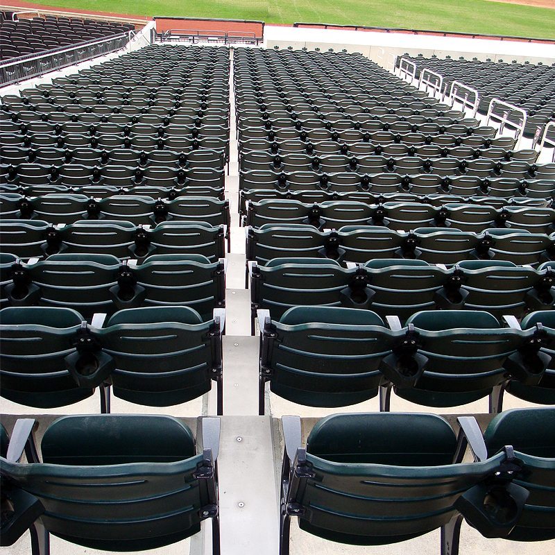
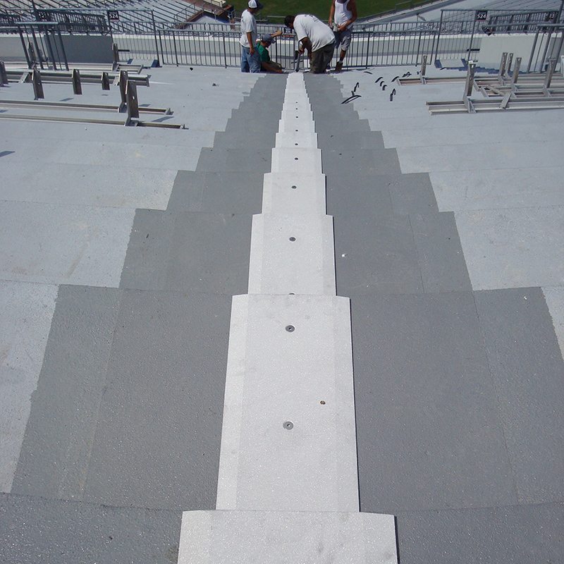
Features Explained
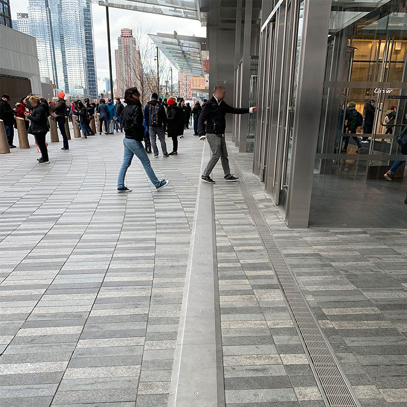
Watertight – The tensionless silicone bellows are installed flush to the mounting height of the system and just below the cover plate ensuring watertightness at the traffic surface. This eliminates the need for ineffective moisture barriers and secondary gutter systems. SJS System is also available specifically for watertight integration with split-slab buried waterproofing systems–see SJS-FP.
Sound Dampened – The flanking impregnated foam and silicone hybrid dampens sound and shock effectively. When installed over EMSEAL-supplied elastomeric nosing material Emcrete, the result is arguably the quietest watertight cover plate system available. (Video: See and hear the SJS difference.)
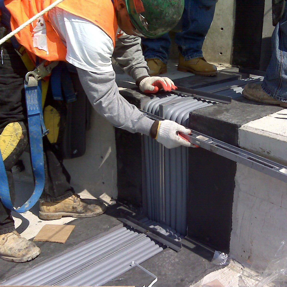
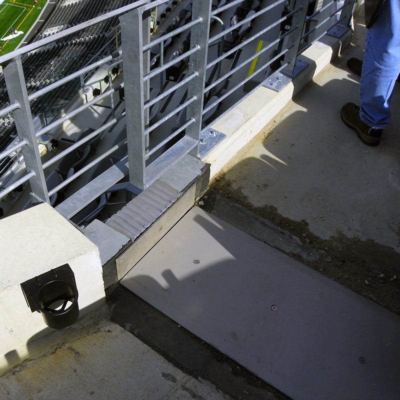
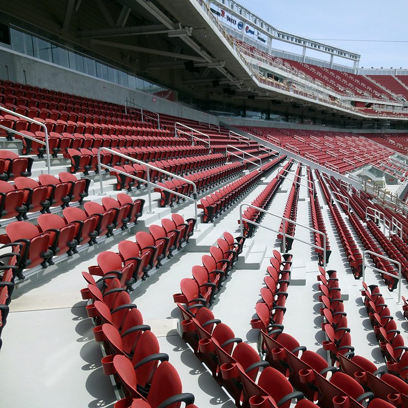
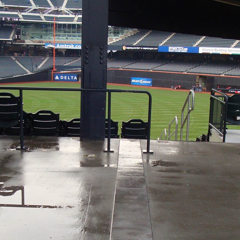
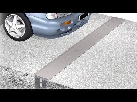
Installs Rapidly – Using non-invasive anchoring the SJS System eliminates drilling associated with hard metal-to-concrete connections as well as intrusive pins, anchors, screws, bolts or tracks, trays or rails. The system is locked to the joint faces by the backpressure of the foam and an epoxy adhesive, and by the injection of a silicone sealant band at the bellows to substrate interface. (Video of installation in a parking deck or a stadium at the New York Mets and the San Francisco 49ers).
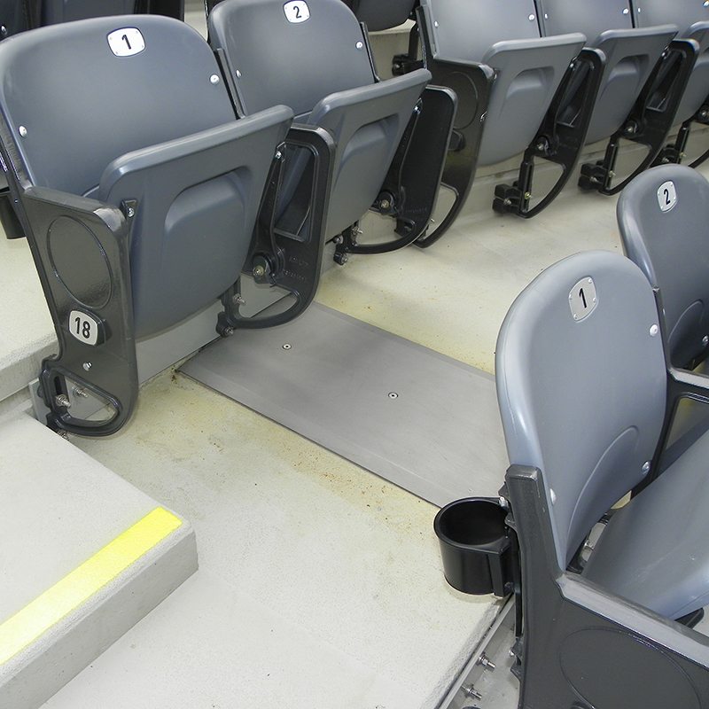
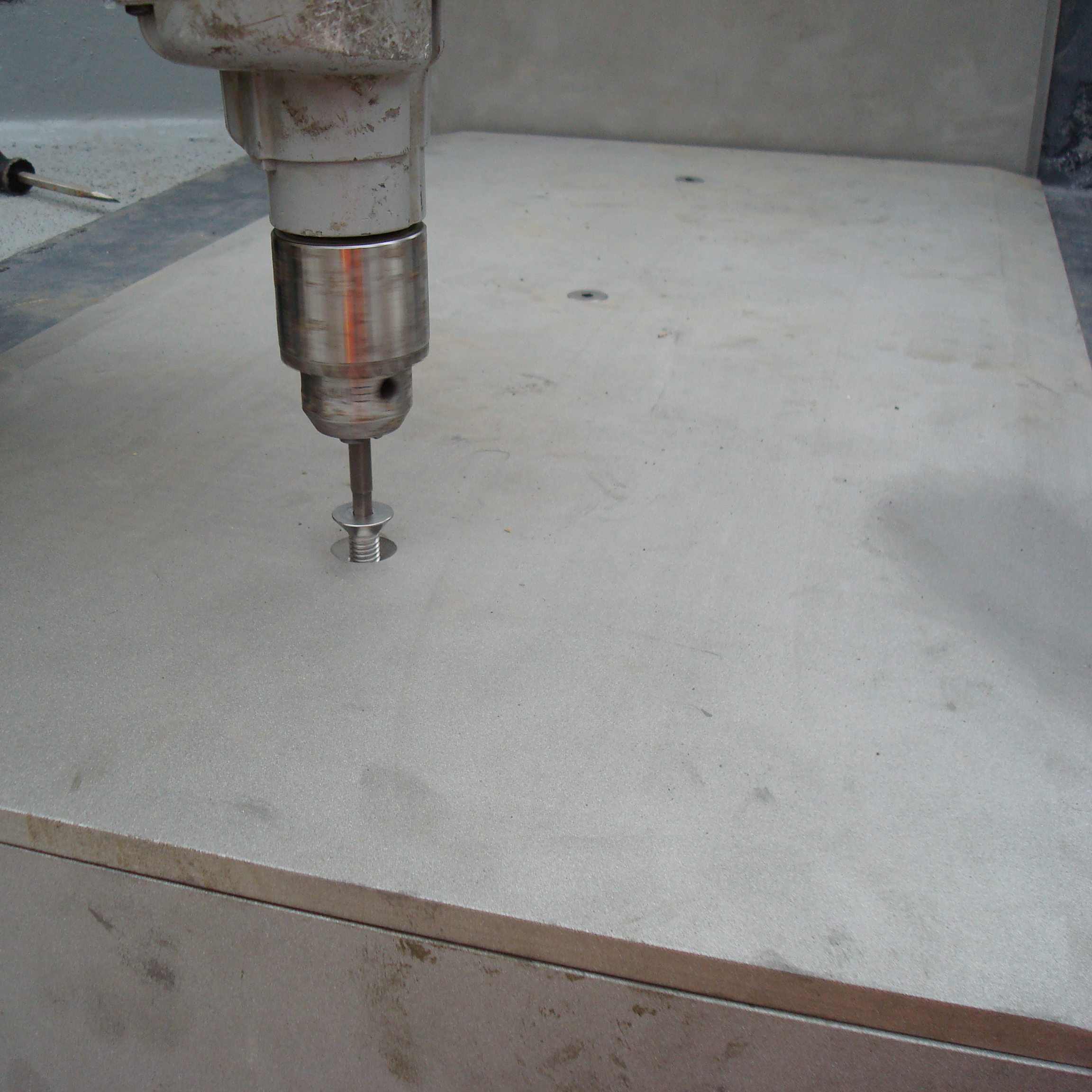
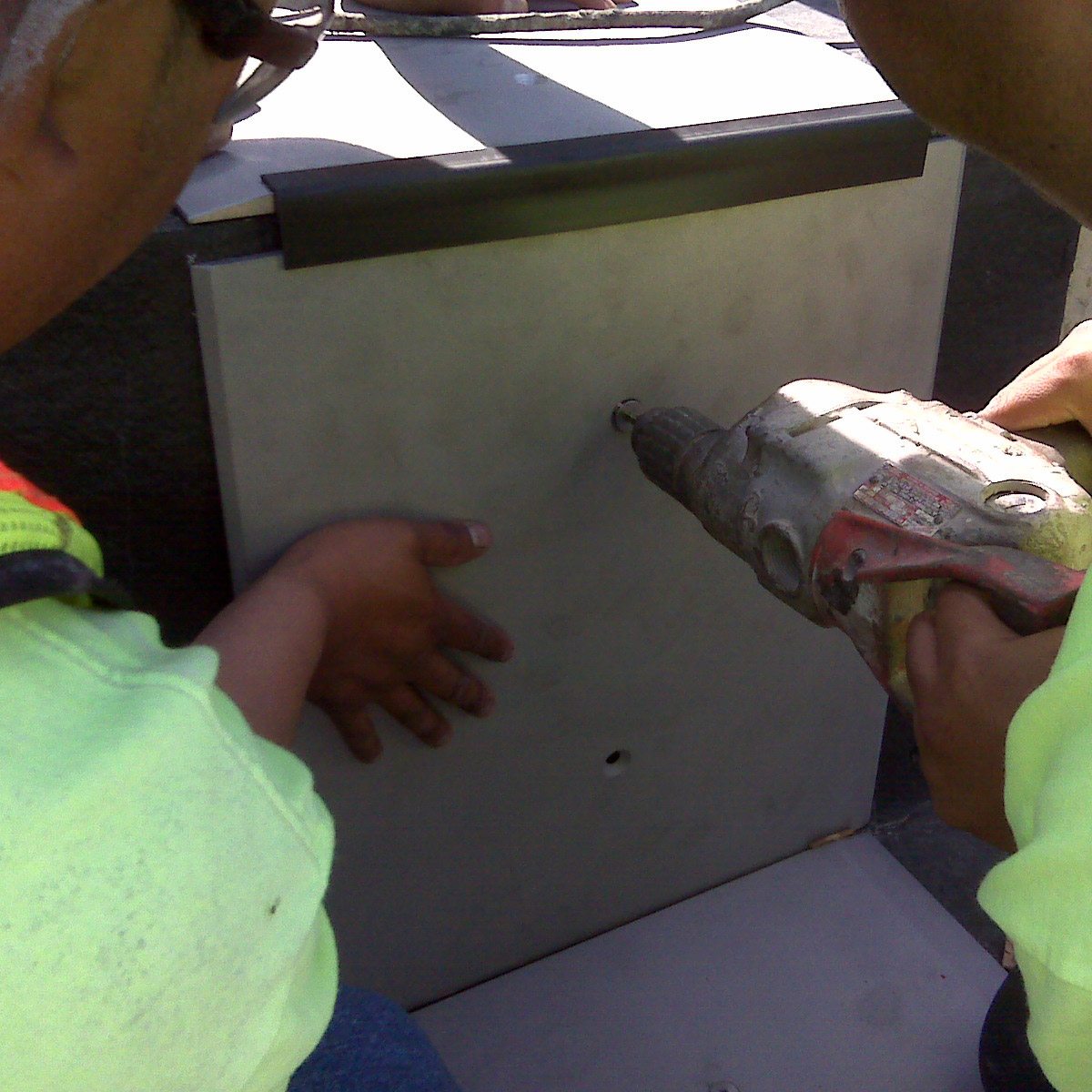
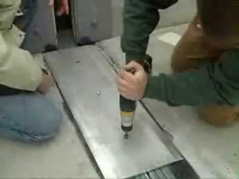
Self-Locating Cover Plate Screws – The center spline is a continuous receptor for the cover plate screws that are self-tapped into the anchor channel. This dramatically reduces the installation-related problems of locating self-centering, sliding ball devices and pantographs. The probability of screws being left out is eliminated ensuring proper anchoring.
Self-Locking, Vibration-Dampened Screws – Vibration in systems that rely on metal-to-metal connections and contact points is the main cause of screw loosening. SJS minimizes vibration through the dampening action of the massive and continuous springs of impregnated foam along the entire length of the joint. In addition, 30 pounds of force is required to loosen the screws offering excellent screw tightness without the need for thread-lock compounds.
Field-Adjustable Plate Support – Concrete in new and retrofit applications is inevitably uneven across and along the joint. The SJS System is installed over a leveling-bed of Emcrete elastomeric nosing material providing the ability to fine-tune the support of cover plate sections. This eliminates plate rocking and noise caused by unleveled plates. Systems that attach or utilize intrusive extruded rails to receive sliding ball plate retention devices cannot be adjusted to eliminate unevenness across and down the length of the joint.
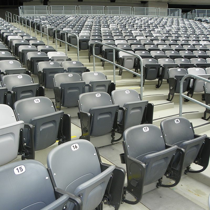
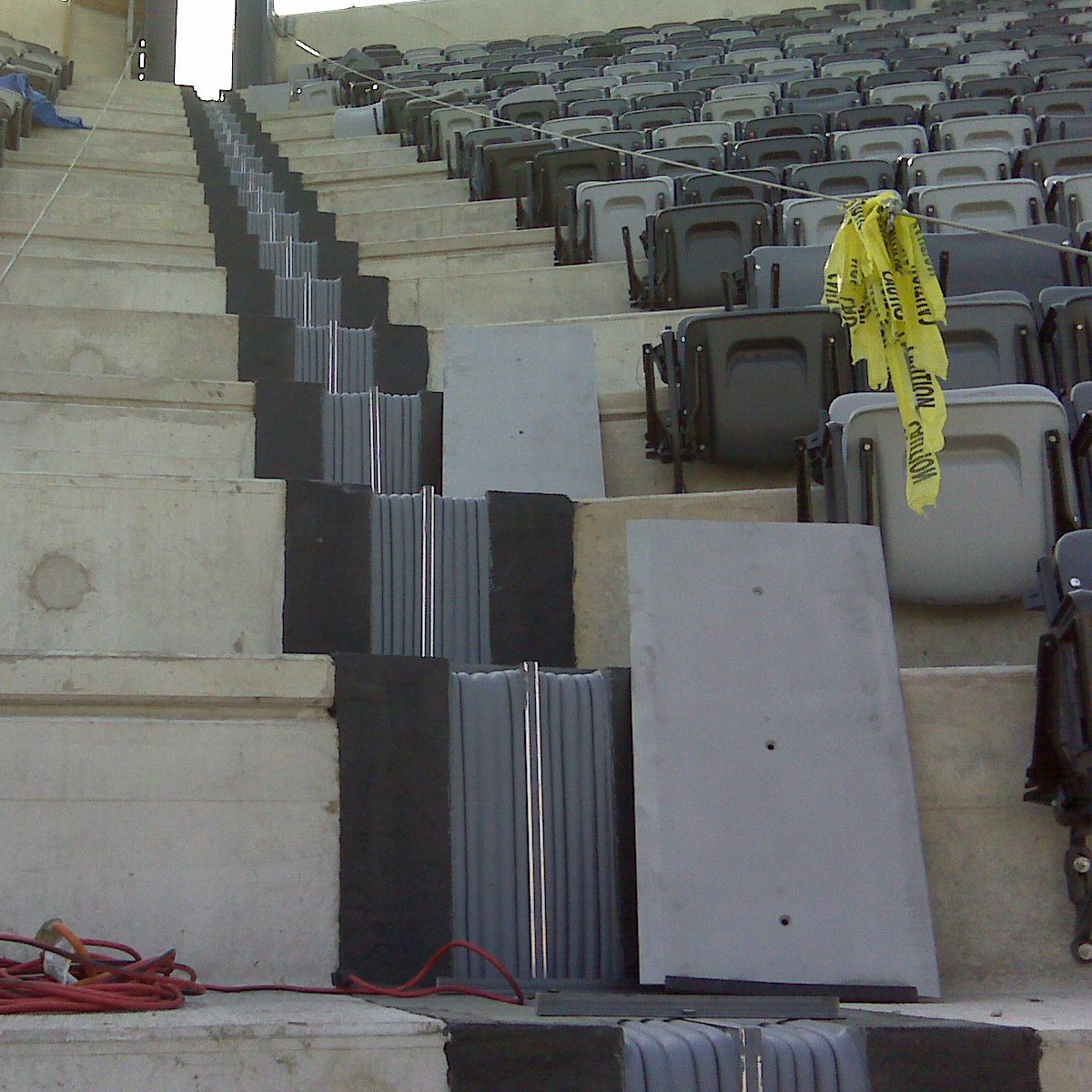
Continuity of Seal – All EMSEAL expansion joint systems feature continuity of seal through changes in plane and direction –– an essential performance differentiator. Interlocking or continuous fabricated transitions for curbs, sidewalks, treads and risers, and parapets for example, are available with the SJS System.
Finite Element Analysis (FEA) Compiled Safety Factors – Prior to field trials, the SJS System was modeled using FEA to determine the suitability of design to worst case possible parking deck loads.
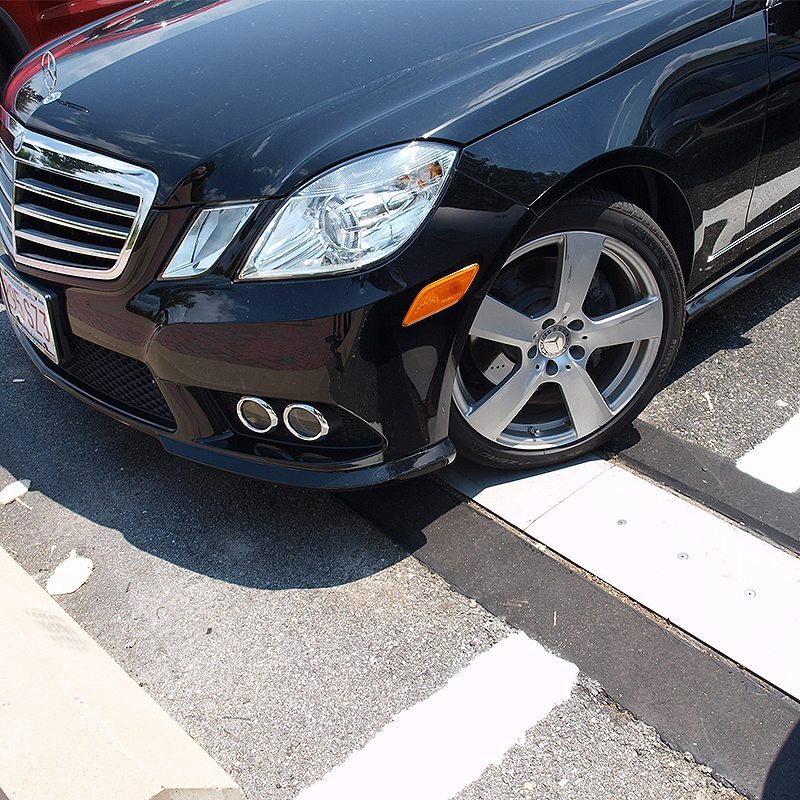
Under the scenario of a 4,000 lb vehicle skidding across the joint system to full stop once past the cover plate, FEA modeling predicted lateral displacement of the cover plate of less than 3/4-inches (19mm) and safety factors in key components as follows:
FEA Safety Factors: Traffic Plate – 5; Screws – 11; Spline Pins – 10; Center Spline – 7
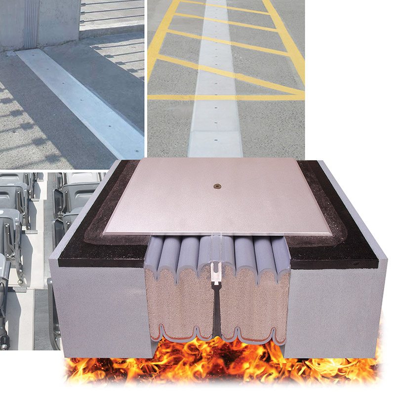
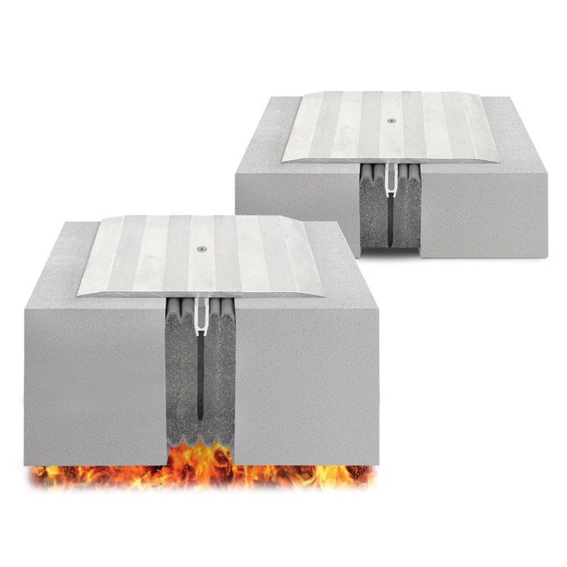
Extreme Conditions — SJS Seismic Joint System is designed to handle the vast majority of heavy traffic and load applications. For high-torque, extremely heavy load applications in traffic decks see SJS-HD and contact EMSEAL. For applications requiring a built-in fire rating, see SJS-FR.
Composition
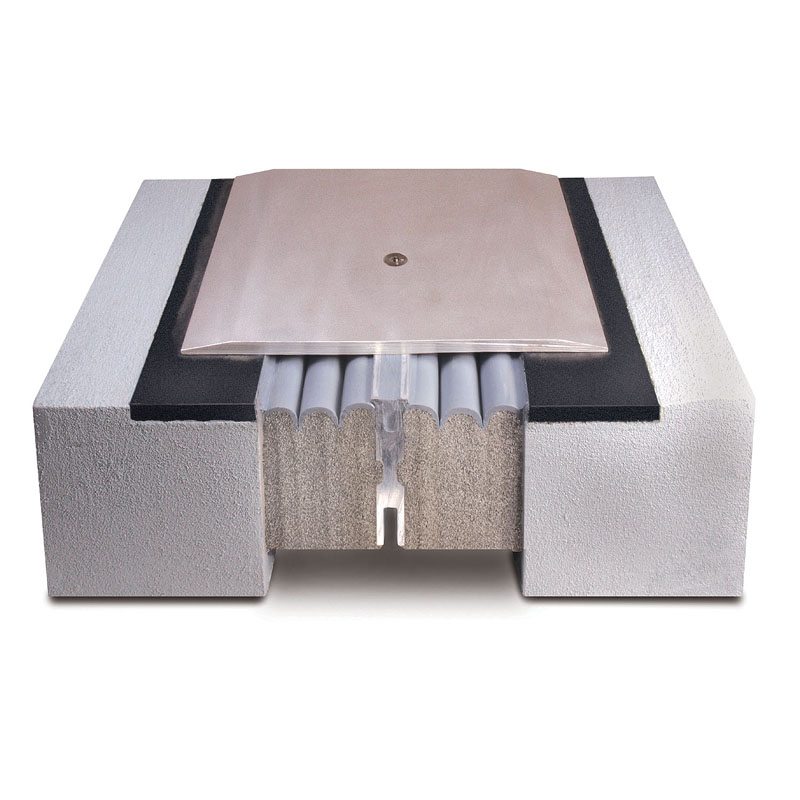
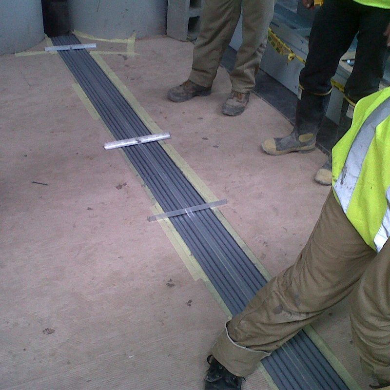
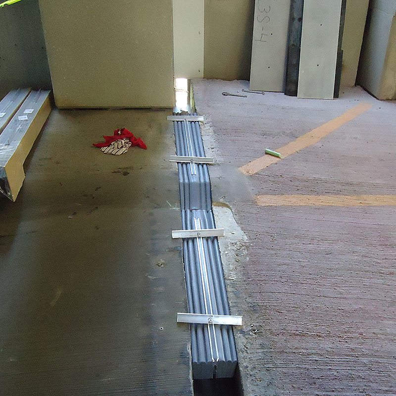
The SJS System is two horizontal precompressed foam sealants pre-assembled in parallel adjacent to a heavy-duty extruded aluminum spline. The spline is designed as the receptor for the attachment of traffic plates that bear vehicle and other loads.
The silicone-and-impregnated-foam hybrid components act to anchor the system, ensure watertightness, absorb sound, and dampen vibration.
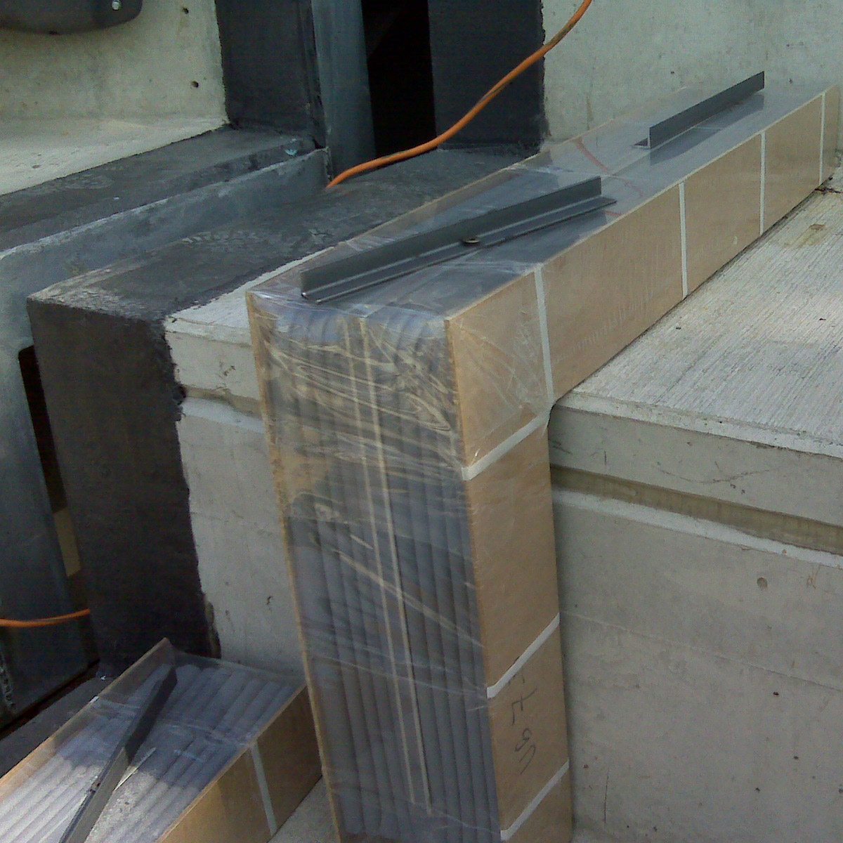
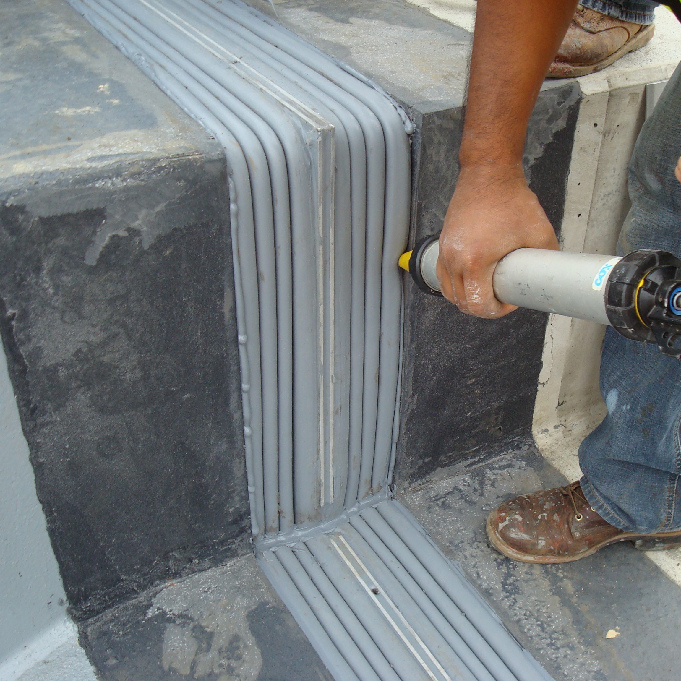
The factory-assembled foam and spline assembly is shipped with factory-attached installation hanger-bars. Epoxy gel adhesive is field-applied to the faces of the joint opening. The sealing assembly is lowered into the joint gap where it self expands into epoxy adhesive.
Consecutive lengths are joined through the field-application of manufacturer-supplied, low-modulus, high-movement silicone to the spline and intersecting bellows surfaces. Friction fit alignment pins prevent the joins from moving during silicone cure. A field-applied silicone sealant band is injected at the bellows to joint substrate interface to seal substrate voids and complete the waterproofing. The SJS joint-sealing assembly installation hanger bars are removed sequentially as coverplates are lowered over the joint and screwed to the center spline, completing the installation.
Design Considerations
- Substrates must be parallel, plumb, have sufficient clear depth to receive the material specified and be capable of resisting approx. 2.5 psi backpressure from the foam.
- Deck surface should be level for proper seating of coverplates.
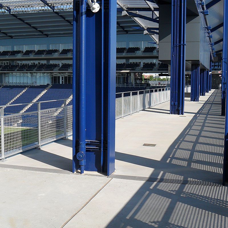
- The SJS System from EMSEAL can be installed in several ways as selected by the designer or owner:
- Surface mounted on top of concrete deck (no recess, no blockout).
- Surface mounted on top of EMSEAL elastomeric nosing material in blockouts on each side of the joint.
- Recessed on top of Emcrete elastomeric nosing material in blockouts on each side of the joint.
Transitions & Terminations
Custom-90’s
(US Patent 9,200,437; 10,066,387; 10,422,127; 10,570,611; 10,794,056)
- Custom-90’s, are factory-fabricated inside and outside 90-degree transition pieces.
- Custom-90’s are available when field conditions and measurements are known up front.
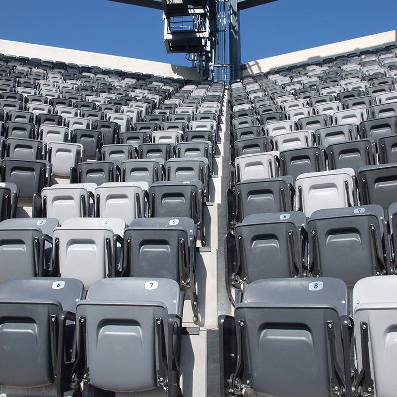
- Custom-90’s are widely used in stadium tread and riser applications or other applications where numerous inside and outside 90-degree transitions are required. Consult EMSEAL.
- SJS System is highly configurable. Transitions at curbs, parapets, toe-kicks and between dissimilar joint systems can be properly sealed with assemblies factory-fabricated to match field measurements.
Maintenance
- As with any construction product, the useful life of the material can be maximized with routine inspection and repair if required.
- Clearing of surface debris and inspection will reveal any damage to the product or adjacent substrates that might affect building performance.
- Repair, if necessary of the system can be accomplished by removing the cover plates and replacing only damaged sections of the foam-and-spline-assembly. Consult EMSEAL to discuss specific conditions.
- In installations subject to snow removal, the detail for recessing the system to flush with the deck should be used. Consult EMSEAL. For guidance on appropriate snow removal practice click here.
Availability & Price
- Available for shipment internationally.
- Prices are available from local distributors or representatives and/or directly from the manufacturer.
- The product range is continually being updated, and accordingly EMSEAL® reserves the right to modify or withdraw any product without prior notice.
Sustainability
Environmental Product Declaration (EPD)
Sika Emseal provides a third-party verified covering its precompressed foam sealants and expansion joint systems (ASTM-EPD1130, valid March 2026 – March 2031).