

SFMTA Castro Station
California
Date: 2026

Designing a Custom Curved Expansion Joint System for Accessibility at SFMTA’s Castro Station
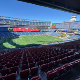
Castro Station Upgrade Overview
As part of ongoing accessibility improvements at the San Francisco Municipal Transportation Agency (SFMTA) Castro Station, Sika Emseal’s engineering team developed a fully custom curved expansion joint system to support ADA compliance along a high-traffic pedestrian walkway surrounding a new elevator structure. The elevated deck connects new construction to existing concrete and follows a sweeping radius within an active urban transit environment. Standard straight-run joint systems could not accommodate the geometry and service conditions of the space. Achieving ADA compliance while maintaining watertight integrity, continuity of seal, and long-term durability required a purpose-engineered solution tailored to the exact conditions of the site.
Design Challenges in Curved Expansion Joint Applications
Transit station renovations introduce unique structural and logistical complexities. At Castro Station, the expansion joint was required to:
- Follow a precise curved radius without faceting or segmentation
- Provide a smooth, pedestrian-friendly walking surface meeting ADA requirements
- Accommodate thermal movement and structural independence between slabs
- Perform under sustained, heavy daily foot traffic
- Integrate with new-to-existing concrete transitions
Off-the-shelf systems are rarely suited to this level of geometric and performance demand. The project required a custom-engineered assembly capable of balancing movement, waterproofing, accessibility, and constructability, all within an active public transit environment.
Engineering a Precision-Fit Curved Expansion Joint System
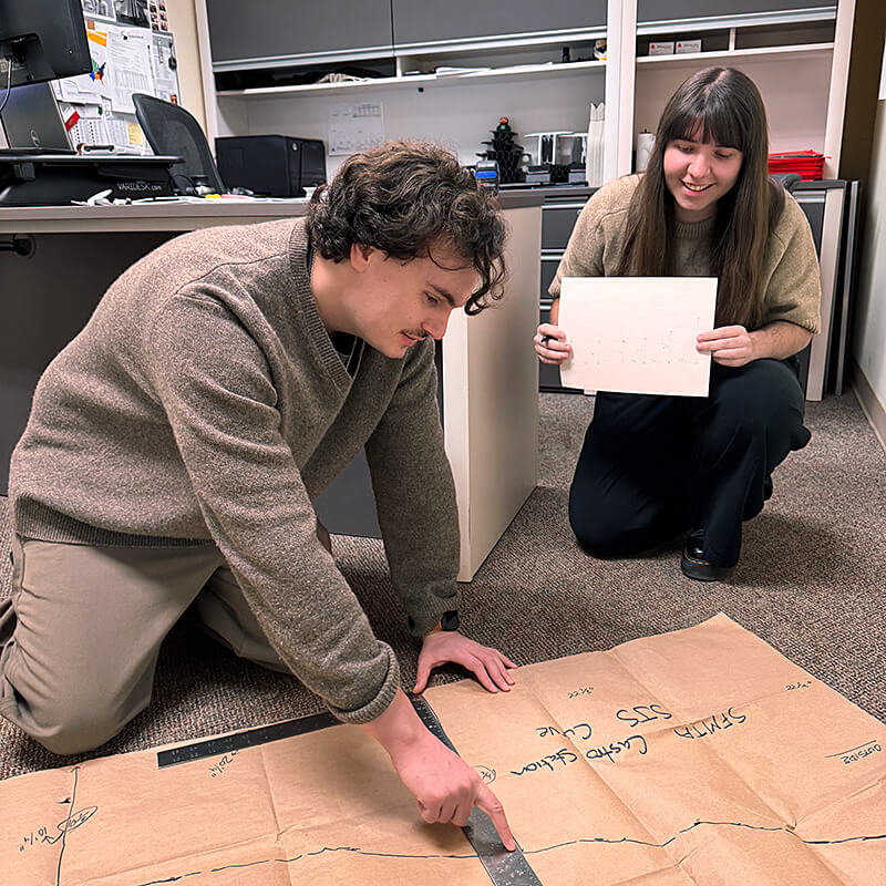
Field-Verified Measurement and Template Development
The engineering process began with comprehensive field measurements taken along the full length of the curved walkway. Rather than relying solely on construction drawings, the team developed full-scale templates to capture true slab curvature, transition points, and dimensional variations present in the field. This verification step is critical in curved expansion joint design. Even minor deviations can compound across a sweeping radius. By grounding the system in field-validated geometry, Sika Emseal ensured fabrication accuracy and minimized installation risk.
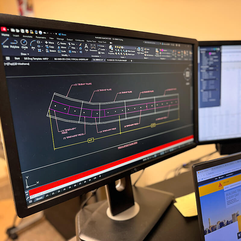
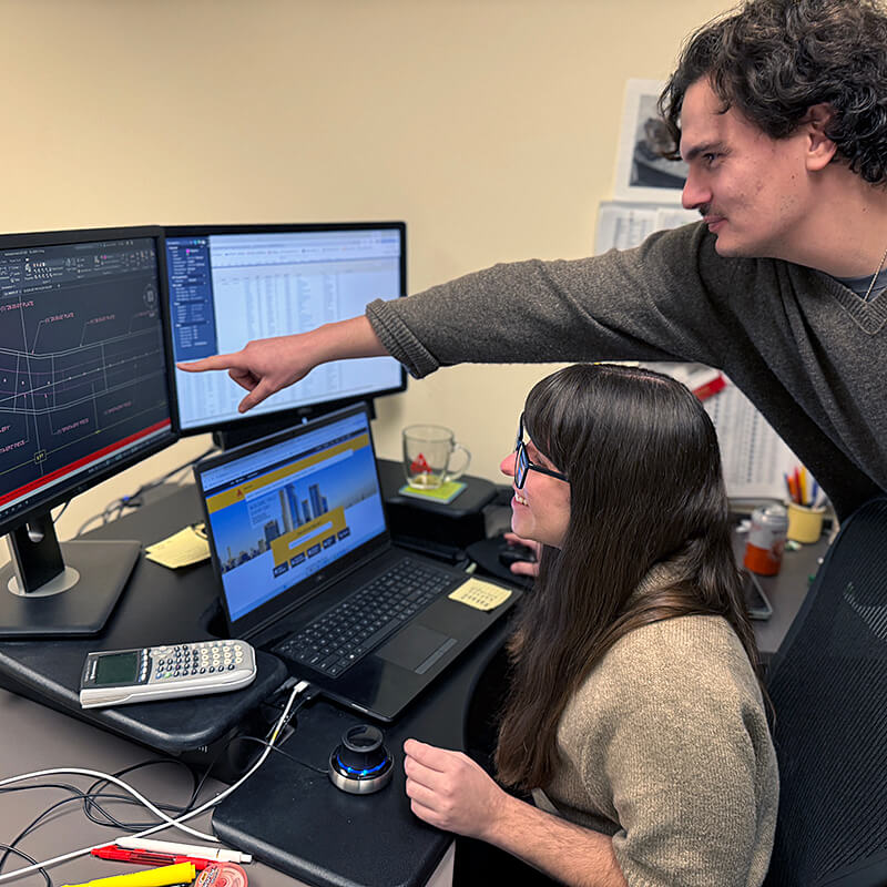
CAD Modeling for an ADA-Compliant Curved Assembly
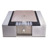
Using field templates as a baseline, the engineering team produced a detailed AutoCAD model of the curved expansion joint and its 28-inch-wide coverplate assembly.
The model addressed:
- Radius continuity and smooth curvature transitions
- Joint-width consistency across the full arc
- Coverplate bend geometry suitable for ADA pedestrian use
- Anchor spacing and fastening patterns
- Tolerances at new-to existing slab interfaces
- Load performance under sustained foot traffic
Field data, templates, and original station drawings were reviewed collectively to verify dimensional accuracy and confirm constructability prior to fabrication. This layered validation process reflects Sika Emseal’s emphasis on engineering certainty before materials reach the jobsite.
Engineering Collaboration
The expansion joint design was led by Sika Emseal’s engineering team, with multiple engineers collaborating on layout verification, curved geometry development, and system detailing. Engineering worked in close coordination with technical sales to support:
- Field measurement verification
- Contractor communication
- Constructability review
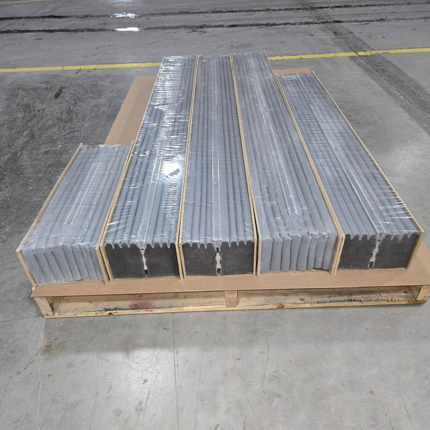
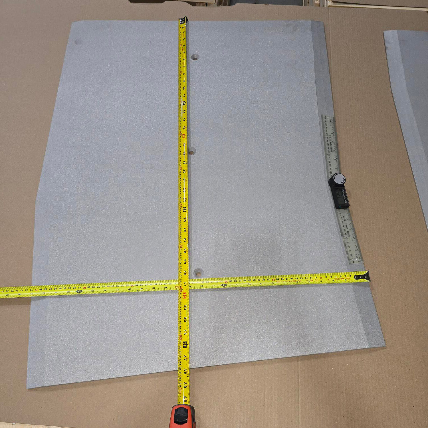
Manufacturing then translated the engineered model into a fabrication-ready curved expansion joint system. Maintaining tight tolerances during forming and assembly was essential to preserving the integrity of the designed radius and ensuring field fit.
This cross-functional collaboration (engineering, technical sales, and manufacturing) ensured the final system was not only precisely designed but also practical to fabricate and install.
Future Installation Update
Fabrication of the custom curved expansion joint system is complete, with installation scheduled for an upcoming construction phase at Castro Station. This case study will be updated with installation photography and field performance observations once the system is fully installed and commissioned.