

Collaborative 3-D Expansion Joint Design
The above blueprint was taken from an actual set of design documents produced by a firm tired of the endless stream of RFI's and change orders that resulted from ignoring or delaying the consideration of expansion joints until during construction. Beyond the delays and cost overruns, their projects additionally typically had a legacy of leaks. Having adopted the EMSEAL approach to expansion joint design, their projects are instead now distinguished by trouble-free expansion joints.
Successful Expansion Joint Treatment—Collaborative, 3-D Design, Detailing, Construction, Fabrication, Installation
It’s not just about products. How can we work together to ensure trouble-free building expansion joints?
While Sika Emseal prides itself on having high-quality, innovative and durable materials for use in sealing, fire rating, and bridging small and large, building component and structural joints in foundations, decks, walls, and floors, the company’s track record of successfully completed projects is equally attributable to the designers, general contractors, and installers who engage in a collaborative approach to expansion joint treatment.
Anybody can make an expansion joint appear watertight in cross-section. However, joints leak at changes in plane, direction and where dissimilar joint materials meet.
Successful projects with expansion joints that don’t leak are characterized by a collaborative commitment by the A/E team, the general contractor, the joint manufacturer, and the waterproofing sub-contractor to think, design, detail, specify, construct, fabricate, and install three-dimensional solutions.
The process begins at design with the visualization by the A/E team and the joint manufacturer of expansion joint locations, layout and impact on all other adjacent materials and spaces.
This visualization is aided by the use of simple isometric line sketches of joint layouts which reveal conditions that could be designed-out, simplified, or for which details must be developed. The A/E then supplements the usual cross-sections with axonometric CAD or BIM details of conditions involving changes in plane, direction and between dissimilar materials.
To these conditions, the expansion joint manufacturer must furnish axonometric or isometric CAD details showing their materials adaptation to these conditions. The manufacturer’s application of their material to the designed conditions should be warrantable as watertight at all agreed upon changes in plane, direction, and intersection between various joint materials. Additionally, the manufacturer can be vetted at design stage for their ability to factory-fabricate, reinforce, and warrant their materials through multi-directional movements including shear. The final isometric layout(s) and all cross-section and isometric details then become part of the bid documents and working drawings.
Before and during construction the general contractors’ role is to elevate the place that expansion joints typically occupy in the sequencing path. ALL trades must be held accountable for their work in relation to expansion joints. The joints, for example, must be protected from construction traffic damage and cannot become a place to accumulate construction tolerances.
The expansion joint subcontractor must commit to taking field measurements from which the manufacturer can fabricate and furnish factory-welded, warranted assemblies to install into the relevant joint locations.
This collaborative approach is not just theory. It is a practice that has resulted in the successful execution of watertight expansion joints on new and retrofit projects on structures of every type.
From the marquee Hudson Yards in New York City, to Oakland International Airport, to the enormous mixed-use—Atlantic Station in Atlanta, to the retrofit of FedEx Field Washington Redskins Stadium, Citizens Bank Philadelphia Phillies Ballpark, Atlanta CONRAC, the Empire State Building retrofit, the new Meadowlands, Mets, Yankees, Titans, 49ers, Raiders, Marlins, Twins, Nationals and over 250 other pro and college stadiums, A/E’s, general contactors, EMSEAL, and a select group of like-minded waterproofing sub-contractors are proving this approach possible and practical.
If this collaborative and disciplined approach is not adopted as the basic philosophy on any project of any scope, whether a stadium, hospital, school, government building or airport, it can be expected that leaks at expansion joints will constitute a high percentage of post tenancy costs and headaches.
We invite you to make EMSEAL your partner in success on your expansion joint projects. Come to our SWRI-Validated Expansion Joint Training or click here to schedule an AIA/CES webinar or seminar in your firm. Or contact us at: 1-800-526-8365 or [email protected]
Think, Design, Detail, Specify, Construct, Fabricate and Install in 3D.
This simple guideline for successful expansion joint treatment starts with the designer and is picked up by the GC, subs and manufacturer. This interactive guide demonstrates how expansion joint technologies tie together through fabricated transitions to ensure continuity of seal.
The following images are taken from the plans of one of the many A/E firms who have discovered that the adoption of this approach can profoundly affect the delivery of a watertight, hassle-reduced project to their clients.
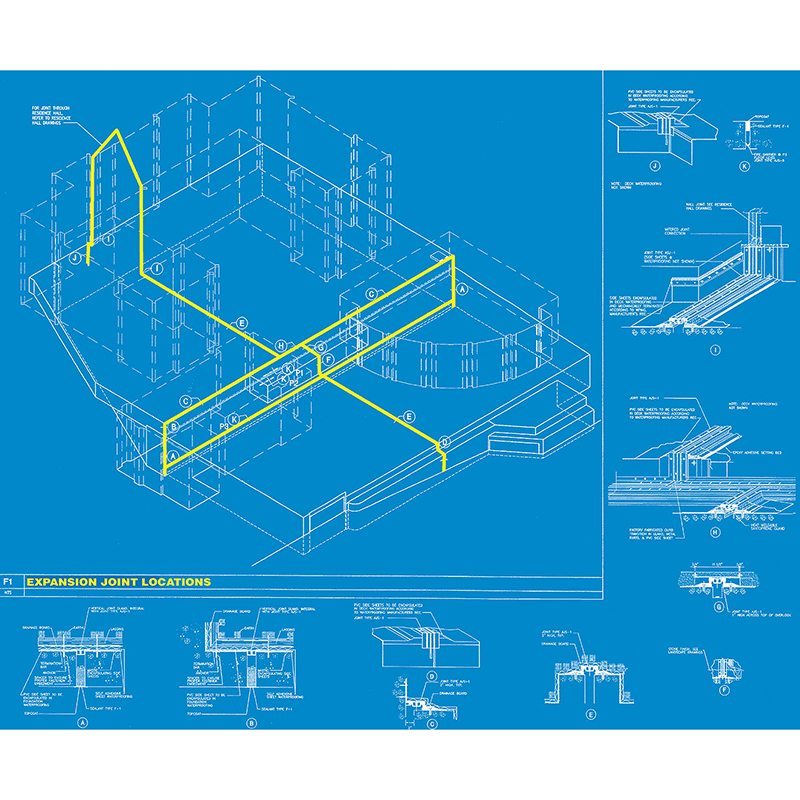
Expansion Joint 3-D Layout Plan
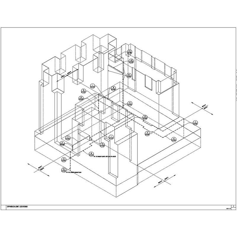
Left: A simple isometric of structural expansion joints on a project can reveal the EJ’s impact on every aspect of the building. This affords the design team the opportunity to simplify the project or relocate the joints or impacted elements.
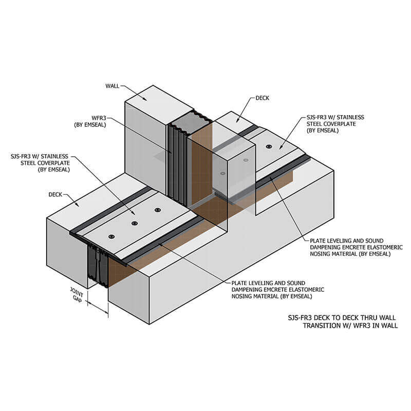
Expansion Joint Details for Transition In and Between Materials
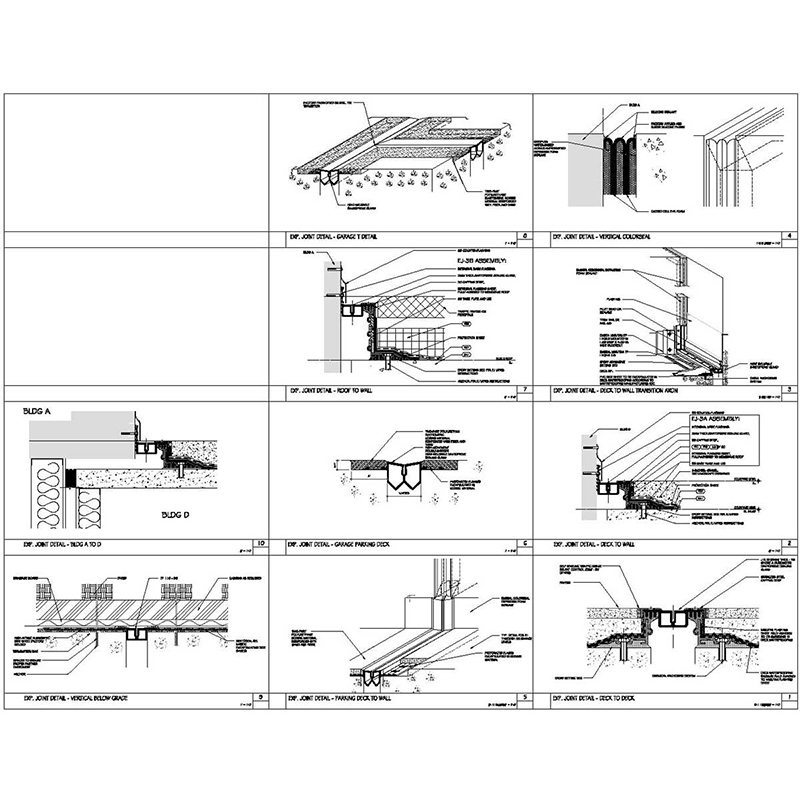
References on the isometric to cross-section and isometric details on a details page show the designers’ intent for changes in plane and direction and treatment of materials at transitions between systems. This allows the sub to include for these transitions in his estimate and reduces time-consuming RFI’s and the costs of change-orders.
For PDF’s of the above drawings, click these links:
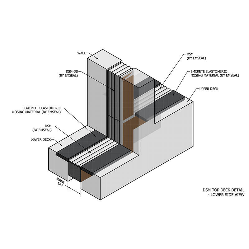
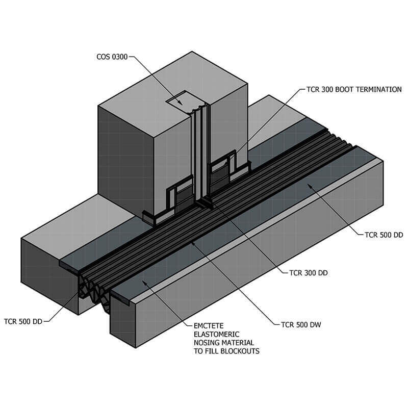
Expansion Joint Transitions 3-D Designed with Inventor
Utilizing 3-D drawings early on in the design phase of the project helps translate how the expansion joint transitions are fabricated. This will also facilitate more accurate bidding by the subcontractors and ultimately a well thought-out and executed waterproof expansion joint transition. The Inventor drawings from the South Boston Waterfront Transportation Center case study is a prime example of the engineering that goes into the expansion joint transitions we provide.