


SJS-Seismic Joint System Installation Instructions
IMPORTANT! Do not install this material until all members of your crew have read and understand these instructions and all related MSDS sheets. If any of the crew do not understand any part of these instructions call EMSEAL:
1-800-526-8365 or 508-836-0280
This product can only fulfill its design function if it has been correctly selected and correctly installed. This means that joint width (after allowance for concrete shrinkage), total joint movement and expected loads must have been considered and accounted for.
These installation instructions are generic and may need adapting to suit specific project requirements and unique conditions. Consult EMSEAL if necessary.
The SJS is a silicone bellows/coverplate system that is anchored to the joint faces of structural expansion joint gaps between flat, level adjacent slabs. Installation will bring the top surface of the SJS proud of the finished deck level by the thickness of the coverplate or slightly recessed where this installation option has been specified, selected, and properly executed.
INSTALLATION OPTIONS
The SJS SYSTEM from EMSEAL can be installed in several ways as selected by the designer or owner:
- Surface mounted on top of concrete deck (no recess, no blockout).
- Surface mounted on top of EMSEAL elastomeric nosing material in blockouts on each side of the joint.
- Recessed on top of EMSEAL elastomeric nosing material in blockouts on each side of the joint.
These installation instructions will discuss the installation of the SJS SYSTEM assuming that all concrete prep and blockout work including the placement of the EMSEAL elastomeric nosing has already been done.
Sections at the end of these installations provide tips on concrete preparation, spall repair using EMSEAL’s elastomeric nosing, leveling of the deck surfaces etc.
It is important that you and all members of your crew read and understand this entire installation manual before proceeding with installation.
TRANSITION and TERMINATION OPTIONS and INSTALLATION
As with any expansion joint system, there are many options for treating the way joints end, transition to other joint system, and are installed at jogs, turns, changes in plane, etc. in the deck.
It is critical to ensuring watertightness that these conditions be addressed in accordance with details provided by the designer and based on EMSEAL approved details and installation methods. Termination and transition details must be disclosed to EMSEAL at time of material ordering so that they can be accommodated in special transition pieces of the SJS SYSTEM to be supplied.
These installation instructions will cover the installation of the SJS SYSTEM in straight runs with reference to generic termination, starting and ending points.
A section at the end of the general instructions will provide tips for installing some transitions. In addition to the general guidelines offered in this document, the job on-site instruction of an EMSEAL field technician should be relied upon for proper execution of job specific termination and transition conditions.
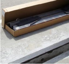
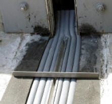
STANDARD SYSTEM COMPONENTS
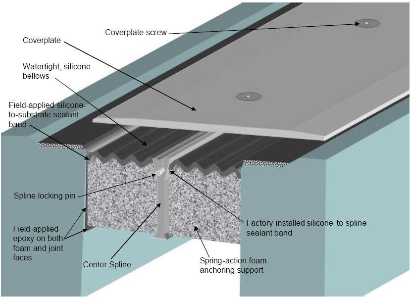
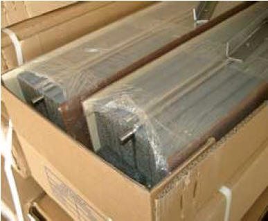
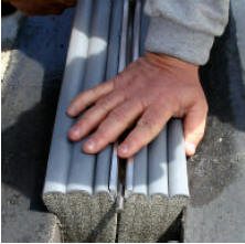
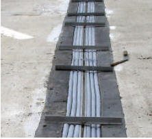
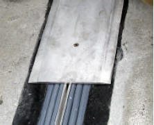
SJS System as supplied—precompressed, shrink-wrapped, with spline pins and installation hanger bars.
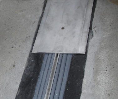
SJS SYSTEM installed with EMSEAL elastomeric nosing material in blockouts on each side of joint gap.
EQUIPMENT LIST for INSTALLATION of SJS-SEISMIC JOINT SYSTEM from EMSEAL
(In addition to normal tools of the trade and safety equipment as required by the installing contractors’ internal safety program and in compliance with local, state and federal safety requirements, the following material and equipment must be on-site before the EMSEAL Technician arrives or before installation can begin):
For Preparing Concrete and Grinding Concrete & Nosing Material
- 4-inch angle grinder(s)
- Diamond cup blade(s) for concrete
- Abrasive blade(s) for metal
- “Zek” wheel pads or 20-grit sanding disks for abrading EMSEAL elastomeric nosing material
For Forming Nosing Material and/or for Spall Repair
- 2-inch Styrofoam extruded polystyrene cut into 6-inch wide strips. (Total quantity 2-times the joint length)
- 2-inch Duct Tape (Total quantity 3-times the joint length) for wrapping the Styrofoam to aide release from nosing material
- “Cherry paper” building felt to mask joint edges (Total quantity 2-times the joint length)
For Cutting and Drilling Aluminum
- “Sawz-all” (reciprocating saw)
- Metal cutting blades for sawz all
- Cutting-oil (“3-in-1” or equal)
- Drill–sizes 3/8” Drill (for drilling new coverplate holes if needed)
- Countersink bits
- Small hand-held metal (fine-toothed) file (for removing metal burrs after cutting)
For Installing and Tooling Liquid Joining Silicone and Sealant Bands from Sausages
- Bulk caulk guns to hold 20-oz silicone sausages
- Bulk-gun nozzles (cones)
- Caulk knives
- Utility knives
For Mixing and Spreading Epoxy Adhesive
- Heavy duty electric, plug-in, drill for mixing thick epoxy
- New, clean, paddles, “jiffy mixers”, for use in electric drill
- Minimum 6 ea – 1 ½-inch wide by min. 8-inch long margin trowels
- Clean or unused plaster/paint pails to mix epoxy, hold cleaning solvents, etc.
For Removing & Installing, Screws in Hanger Bars and Coverplate
- Hi-Torque, electric Drill-Driver(s)–to remove and reinstall stainless steel screws. Drill-Drivers instead of drills are required to help prevent over-tightening the screws
- minimum 6 ea – 7/32-inch hex bit socket drill drivers (3/8-inch drive)
- 3/8-inch socket adapters (for use in drills)
- Heavy hammer (3-pound) to tap end of spline to set spline pins at opposite end of stick)
- Torque-Wrench—long handled 3/8-inch socket with adapter to accept #3 screw-gun tip. Note: torque wrench must accurately read as low as 60 in-lbs (5.2 ft-lbs; 7 Nm) and as much as 240 in-lbs (20 ft-lbs; 27 Nm) – (for final torque setting on capping strip and cover plate screw).
Other Miscellaneous Tools and Materials
- Levels, 2-foot, 4-foot, and torpedo-level
- 100-foot tape measure
- 1 box of lumber crayons (to mark high spots for grinding)
- Combination square
- Chalk box with chalk
- Flat bar and small pry bar
- Pail of cleaning solvent (Toluene or equal) (depending on the size of the job, less toluene may be adequate)
- Box of clean, dry, lint-free, 100% cotton cloth (not paper) rags
- Shop vac
- Extension cords
- Generator or reliable electrical source
- High-pressure blowers to clear debris
STORAGE and HANDLING:
(NOTE: The precompressed foam in the SJS system will expand faster when hot and slower when cold.
On hot days Above 60°F (15°C):
Keep the material in its cardboard shipping cartons, out of direct sunlight (preferably on an intermediate, shaded deck. If no shade is available on a really hot day, keep the material inside an air-conditioned job van, or open the lids of the shipping cartons and lay bags of ice over the material. This will give you more working time.
On cold days Below 41°F (5°C):
If it is sunny out, open the cartons and set the material in the sun. Or, keep the material in a heated job-van until immediately prior to use.

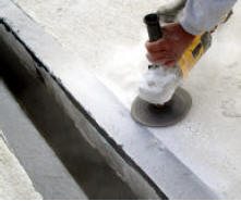
1) Use grinders to remove all bumps, and protrusions of concrete from joint faces
Concrete:
- Remove loose particles and weak concrete to ensure sound concrete substrate. Spalls, chipped edges and uneven surfaces must be repaired using suitable patching material and proper patching geometry and techniques. Joint faces must be parallel. Joints must have unobstructed depth greater than or equal to the full depth of the largest material supplied plus 1/2-inch (6mm).
- Remove all contaminants by sandblasting or grinding to ensure a thoroughly clean and sound substrate for the full sealant depth. NOTE: DO NOT use a wire wheel–this will polish the substrate and cause bond-failure.
- Dry all wet surfaces. NOTE: If a flame is used to dry substrates this will leave carbon on the substrate and cause bond-failure. Grind and clean the surfaces to remove carbon.
- Wipe joint faces with solvent-dampened, lint-free rags to remove all concrete dust and contaminants.
Metal:
- Sandblast or grind to rough, white metal and solvent-wipe immediately prior to applying SJS epoxy.
IMPORTANT: Ensure that no oxidation (rusting) occurs before the epoxy is applied.
Other Substrates: Contact EMSEAL.

2) Prep and repair any spalls at the joint edge and at the back edges of the blockout with appropriate repair material and repair geometry.
(NOTE: Repair of spalls is best done using EMSEAL elastomeric nosing material. This material is flowable, self-leveling, and fast curing. If your project is to use the installation option that involves installing a nosing material as a low-friction, sound reducing, support for the cover plate of the SJS, then spalls can be repaired in a single step along with filling the blockout—see “Installing Nosing Material” section, Page 10.)
3) Using wire brushes, blowers, and solvent wiping, remove all dust and debris from joint faces.
(NOTE: This step is critical to ensure that the epoxy adhesive bonds properly to the joint faces. Any dust or debris left on the substrates could cause a bond failure).
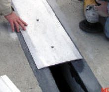
4) Ensure deck heights are the same across joint-gap and that there are no obstructions to the free movement of the cover plate.
(NOTE: Place coverplate sections across the joint opening. Remember that the joint will close during summer heating. This means that when closed, the cover plate must be free to slide on both sides of the centerline of the joint opening. Any cured lumps, lips, overpours of concrete, will prevent free movement. Grind these off using diamond cup grinders).
5) Ensure deck is even and flat along its length on both sides of the joint.
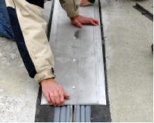
Cover plates are supplied in standard 5-foot lengths. In order to be fully supported and to prevent rocking, the deck or nosing surface must be level across the joint for the full length of each plate.
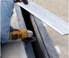
This is achieved by laying out the cover plates over the joint opening along the entire length of the joint. Then by putting pressure on one edge of a plate, push down on the opposite side. If the plate rocks, identify where the high spot(s) are under the plate. Lift the plate and mark these spots using a lumber crayon. Use a grinder and ‘zek’ wheel or 20-grit sanding disk to remove the high spot(s). Place the cover plate back over the location and repeat the process until the plate lies flat and no rocking can be produced.
(NOTE: This leveling process is easily achieved when the EMSEAL elastomeric nosing is used. If installed directly onto concrete, this process will require you to grind the concrete using diamond cup grinders).
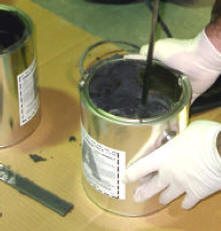
6) Mix one kit of epoxy adhesive and apply a thin coat (no more than 1/16” thick) to both joint faces to a depth of 4-inches (100mm)—be sure to extend epoxy between parapet or split column faces of transitions to upturns.
Mixing Epoxy:
- EMSEAL epoxy adhesive may be used in the 41°F (5°C) to 95°F (35°C) temperature range.
- Using a trowel, transfer the entire contents of Part B (hardener) into the contents of Part A (base).
- Mix the material thoroughly with a drill and mixing paddle. Scrape the walls and bottom of the container to ensure uniform and complete mixing.
- Always mix component B (hardener) into component A (base).
- Ensure that a uniform gray color with no black or white streaks is obtained.
IMPORTANT: DO NOT thin the epoxy.
Ensure that the mixed epoxy adhesive is applied to the substrate before the pot life has expired (10 – 30 minutes depending on the ambient temperature).
WARNING: Epoxy will harden more quickly when left in the pot–get it onto the joint face as soon as possible.
IMPORTANT: The epoxy must still be uncured when installing the SJS into the joint-opening.
If the epoxy cures before installing the SJS then reapply new epoxy. If work is interrupted for more than 2 hours after initial cure then grind the old epoxy and apply new wet epoxy.
NOTE: If preferred, you may use a bulk gun to draw up and apply epoxy to the joint faces and to the side of the foam before spreading it with the margin trowels.
IMPORTANT: While one or more workers are applying epoxy to the joint faces, others must prepare the SJS assemblies.
7) Prepare a “starter piece” of SJS, to suit the transition or termination detail suitable to the joint as agreed in discussion with EMSEAL and EMSEAL field technician.
NOTE: Starter pieces and end pieces are custom configured based on the needs of the particular installation. Usually they have and end where the center spline stops short and the last six to eight inches is foam only. This allows you to trim, notch and bend, or miter the foam to suit termination requirements.
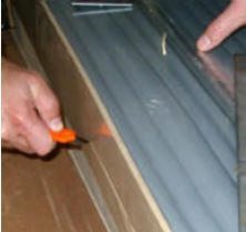
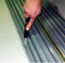
8) Open SJS system “starter piece” by cutting shrink-wrap by running a utility knife along the hardboard sides.
Remove and discard shrink-wrap and hardboard. (DO NOT cut along silicone bellows surfaces).
IMPORTANT: Work quickly and deliberately after cutting the shrink-wrap to avoid material expanding beyond a usable size.
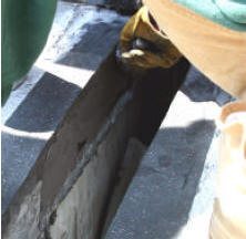
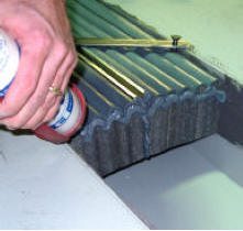
9) Using margin trowels apply a “scrape” of epoxy onto both outer faces of the foam.
10) Allow foam to expand to the width (or slightly greater) of the joint opening so that when lowered it fits snugly into the wet epoxy on the joint faces and does not sag below the lip of the blockout.
11) Rotate joint hanger bars to hold the joint assembly in place.
NOTE: If needed on larger joints, center the joint assembly in the joint by installing hanger screws into the outer holes in the joint hangers and rotate the hangers so the hanger screws wedge against the joint faces.

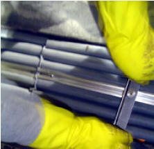
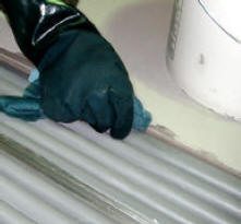
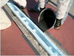
12) Using a sausage caulk gun, nozzle, and the silicone sausages supplied, apply a thick (1/8”) bead of liquid silicone to the face of the spline and onto the foam along and ½” (12mm) below the silicone bellows.
13) Unpack next material assembly, apply epoxy to the foam faces, and lower it into the joint sliding it up to align with the already installed piece.
Make sure the chamfered end of the joining pin sits in the channel of the previously installed spline.
Ensure the splines of each length are snugged up against each other.
(NOTE: Some of the silicone tooled to the face should squeeze out between the bellows faces).

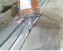
14) If the spline pin did not seat all the way in step 13, using a 3-pound hammer, tap the end of the spline away from the join to ensure that the spline-pin is driven all the way into the previously installed length. (Note: liquid silicone should squeeze up out of the join).
15) Using a caulk knife, tool the joining silicone into and across the bellows.
If necessary, use the caulk gun to apply additional silicone to the join between the two lengths and tool excess from surface and between wrinkles of the bellows.
16) Repeat process until all lengths of joint assembly have been installed.
17) Using lint-free cotton rags and solvent clean the silicone bellows next to the joint faces to receive the silicone sealant bands and corner beads.
18) Using the same procedure as with the “starter piece”, cut the “closing piece” to length by trimming the foam-only end. Address the transition or termination of the end of the joint as agreed in consultation with EMSEAL.
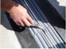
19) Using the bulk gun and sausages provided, inject silicone sealant bands between the foam, silicone bellows, and joint faces. Inject a deep (minimum ¾” (20mm)) band of liquid silicone.
(NOTE: Rotate hanger bars as you go so you can install a continuous corner band of silicone).
IMPORTANT: On installations of long runs of material, have one worker drop back after the installation of the first 2-3 lengths to follow along and carry out step 17 and 19.
20) Using a caulk knife, tool the silicone into a corner bead between the top of the silicone bellows and the joint face.
21) Starting at one end of the joint, remove the first one or two hangers to make room to install the first section of coverplate.
22) Lay out cover plates next to the joint to identify starting and finishing plates (these are usually shorter than the standard lengths).
23) Place the first section of coverplate over the joint assembly and line up the screw holes over the channel in the spline.

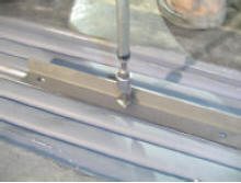
24) Using a drill-driver and 7/32” hex bit socket, drive the coverplate screws into the spline channel until tight. Ensure that the spline is drawn up snugly against the underside of the coverplate. If necessary, use a hand socket wrench and handle extension to do the final tightening.
CAUTION: Driving the cover plate screws requires a lot of torque. Be sure to have a firm grip on a supporting handle on the drill driver. Be sure to brace the drill as needed to prevent it from spinning and causing injury.
25) Remove next joint hanger(s) as needed and install coverplate sections until installation is complete with the installation of the final finishing cover plate.
26) Manually tighten coverplate screws to final torque
It is critical that the top of the spline be pulled up tight to the underside of the coverplates.
To achieve this, you must use a torque wrench and tighten each screw to 240 in-lbs (20 ft-lbs; 27Nm).
IMPORTANT: Fully and firmly insert the hex driver into the screw. If you don’t you will strip the screw head.
TIPS for working with EMSEAL Nosing Material
- Wrap Styrofoam form strips with duct tape to make removal easier
- Place a Styrofoam form against each joint face and insert Styrofoam wedges between forms
- Prime blockouts and spalls with EMSEAL-supplied primer
- Mix nosing material in accordance with on-site instructions from an EMSEAL field technician.
Pour nosing material into blockouts to level with bottom of concrete chamfer or to within 3/8-inch from deck surface. Use nosing material to ensure blockouts are level from one side of the joint to the other. Use nosing material in this step to ensure blockouts are level along their length.
Blockouts can be filled flush to the deck or recessed by the thickness of the cover plate supplied.
TIPS for transitioning SJS to COLORSEAL in parapets, split columns, and wall joints
- Follow the on-site instructions of an EMSEAL field technician for the proper execution of all transitions and terminations.
- Insert this foam-only end between the faces of the parapet walls or split columns into the wet epoxy being sure to push it in to the depth of the vertical foam to join it from the vertical plane.
Site Fabricate Transitions and/or Connect Factory-Fabricated Transitions
If the system contains special pieces or transitions such as tees or right angles, these must be site-measured, cut and fabricated (or connected if factory-fabricated) at this stage to complete the system.
NOTE: If starting at a transition (Upturn, Flat 90o etc) join the first full length to the already installed transition piece.