

Air Barrier Gaps
Is There a Gap in Your Air Barrier Wall Design?
Overlooking joint sealing where it really matters–in the structural backup wall.
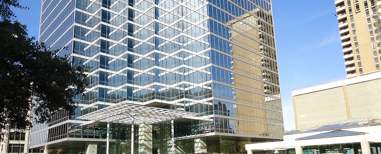
All day long, our specification development team opens and reviews architectural details. We look at cross sections every week. One of the most often seen reflects the industry’s move towards exterior wall design based on air barrier principles.
Driven by the desire for more energy efficient buildings and LEED certification, air barrier codes were developed and adopted in Canada years ago and have been adopted in states across the US. The principles of air barrier design are being widely adopted because they make sense–building science, waterproofing, and energy-use sense.
What do we see?
One of the details we see repeatedly shows a plan-section through the wall at a structural expansion joint (see Figure 1). This can be at the mid-span or elevation change of the building or, as commonly, at additions between new and existing structures. The detail shows the structural backup wall, sometimes block, sometimes steel-stud and exterior gypsum. The structural wall is wrapped or coated with an air barrier membrane and extruded, polystyrene insulation board is detailed over the air barrier. The cavity-wall gap comes next and then the exterior façade material—often brick, but also precast concrete, metal panels, etc.
At the structural expansion joint in the façade we very often see detailed Seismic Colorseal—a structural expansion joint hybrid sealant that fills these larger joints, insulates them, makes them watertight, coordinates through color with the aesthetic of the building, and installs without the use of invasive anchors.
The Problem:
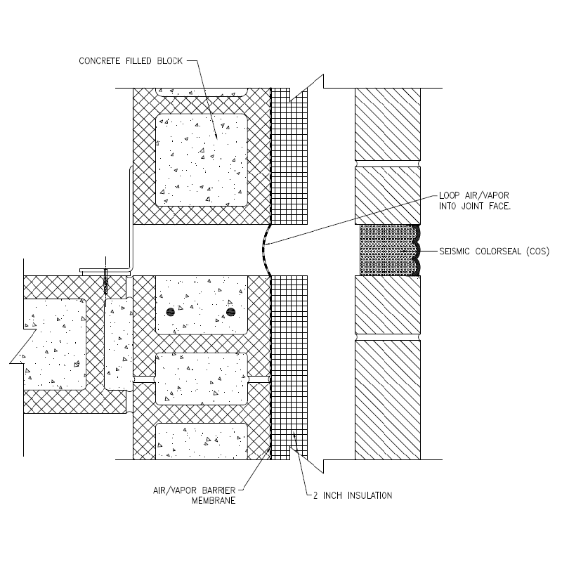
Figure 1:
Typical detail shows 2″ expansion joint gap in precast facade, wall cavity, extruded polystyrene insulation, air barrier membrane, CMU backup wall. Note air barrier membrane looped into joint and lack of insulation at the structural joint in the backup wall.
Where’s the problem?
In the structural joint in the backup wall we see a sliver of air-barrier membrane or other “tape” across or looped into the joint. The structural joint gap itself is empty. On some details the gap is shown filled with something — usually fiberglass batt insulation. All three of the these is a problem.
Firstly, this gap is a dynamic, moving, opening and closing structural expansion joint. It will cycle continuously throughout its life. Air barrier membranes and joint bridging “tapes” if installed without any slack will tear. Even if installed as drawn with a loop into the joint, these products will fatigue and tear where they wrap around the joint corners. These materials are not designed to handle joint cycling and are particularly prone to failure when they become brittle at low temperatures.
Secondly, membranes and tapes provide no insulation. The detailing of extruded insulation board in the cavity is intended to insulate the wall from the outside of the structural wall. This means that at the structural joint gap, instead of a thick piece of insulation board all you have is a few mils of modified rubber sheet between the cold wall cavity and the inside of the building. The structural joint gap is a direct path to the interior of the building. In this detail, the joint-gap constitutes a major gap in thermal insulation and could be setting the R-value for the entire exterior wall system.
As was pointed out in “Exterior Wall Systems, R-Value, and Revenue” by Tom Kuckhahn published in the September 2003 Construction Specifier, heat “seeks the path of least resistance, so the R-value of an actual wall is closer to the R-value of the least insulating portion of that wall.”
Furthermore, in details where the structural joint gap is left unfilled, condensation can form on the interior side of the membrane, thereby trapping moisture in the wall.
The use of fiberglass batt insulation to fill this cavity invites two problems. Fiberglass insulation cannot handle joint cycling. It takes on compression set and loses much of its insulation value. Once set and no longer properly insulating, it is still porous and will absorb moisture that condenses behind the uninsulated membrane “bridge” across the gap.
What to do?
An elegant solution to this gap in air-barrier wall design is to detail a preformed, impregnated, cellular foam sealant in the structural joints in the structural wall, as well as in the facade. Seismic Colorseal is the product to use both in the backup and in the facade. It is watertight, provides 100% movement capability, excellent sound attenuation and, of course, R-value.
The Solution:
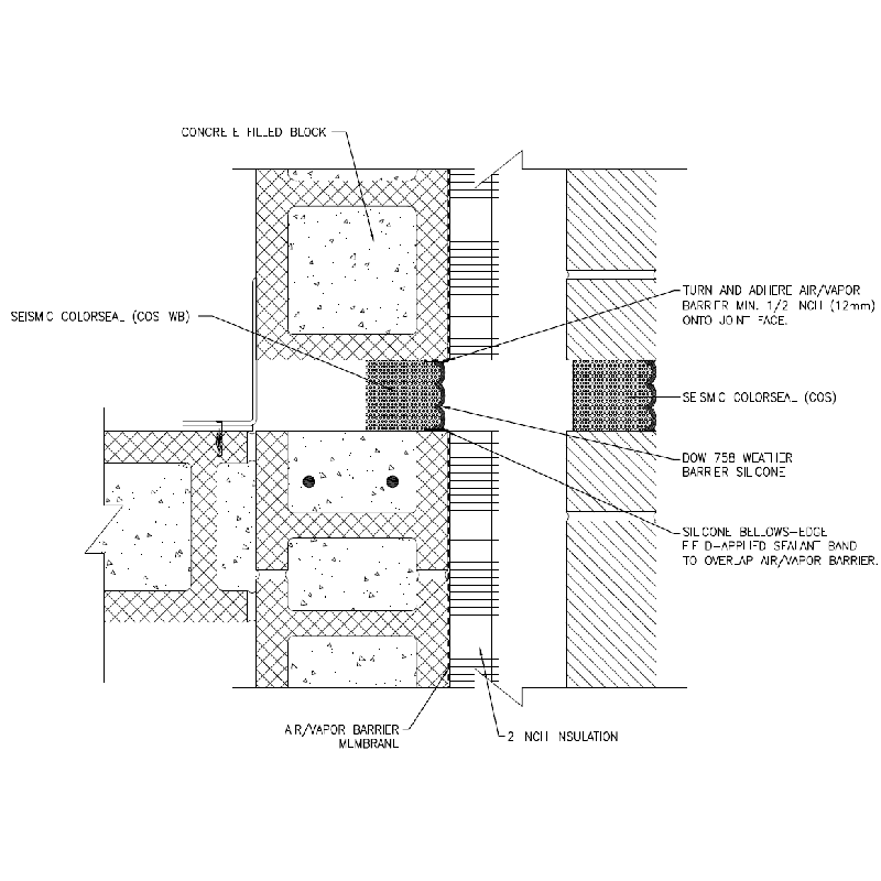
Figure 2:
Seismic Colorseal installed in the backup wall ensures:
- continuity of the air barrier,
- continuity of thermal insulation, and
- continuity of waterproofing
The R-value of Seismic Colorseal is 2.15 per inch of depth.
This means that on the above typical 2-inch joint, the R-value at the structural joint gap sealed with Seismic Colorseal is:
2.15 x 2.5 (the depth of seal of 2-inch Seismic Colorseal) = R-5.75.
On a typical 3-inch joint, the R-value at the structural joint gap of a wall sealed with Seismic Colorseal is:
2.15 x 3.5 (the depth of seal of 3-inch Seismic Colorseal) = R-7.52.
Installed on both sides of the interior wall, this value will double to R-15.04 excluding the R-value of the air-space created between the two pieces of Seismic Colorseal.
Design flexibility is further extended through the option to customize the depth. With each additional inch of depth, you are adding more insulation.
And, double-sided Seismic Colorseal (COS-DS) provides the option to seal both faces of a wall system in a single step. In this way you can eliminate the interior wall cover as it would be replaced with the inner bellows face of the COS-DS.