


Hospital and Healthcare Expansion Joints
More than Just Bridging the Gap: Selecting Floor Expansion Joints for Hospital and Healthcare and Medical Facility Traffic Conditions
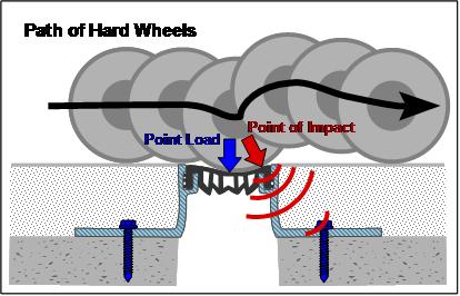
Floor expansion joints must be engineered to withstand the specific movements and stresses they will encounter. In healthcare floors, any failure can be unsightly, noisy, dangerous for people and harmful to expensive mobile medical equipment. The number one cause of damage to interior floor expansion joints and surrounding floor materials is point loads of equipment fitted with hard, small-diameter wheels.
Yet despite the destructive impact of high point loads on healthcare floor joints, this factor is frequently ignored. Many expansion joint manufacturers fail to rate the point load resistance level for their products under various wheel types, making it difficult for architects, engineers, contractors and building owners to make informed decisions.
Selection Criteria
Point load resistance is one of three criteria for selecting a suitably engineered floor expansion joint. Whether in new construction or retrofitting failed existing joints, the questions that should drive product selection include:
- Movement: Can this model handle the expected thermal and other movements of the building?
- Joint-Gap Size: Does this model have the correct dimensions to straddle the designed joint-gap?
- Point Load: Can this model handle the wheel and axle loads from the expected traffic?
Hard, plastic tires–the type most prevalent in hospitals–place the greatest stress on expansion joints. In a survey of the web sites of seven floor expansion joint manufacturers, only one, www.emseal.com, provided comprehensive loading data, by wheel type, for joint systems offered as “heavy duty” or “high point-load.” Four of the Web sites made no mention at all of wheel loading capabilities. Two others made a cursory mention of total loads possible for just one of each of the many models offered as “heavy duty” but with no correlation to wheel type.
The MIGUTRANS series of expansion joints on www.emseal.com are offered specifically for the ability to handle point loads. The FS 110 model, for example, shows a load capacity, for equipment with solid, hard-plastic tires, of 365 lbs/inch width of tire (6.5 kg/mm, 63.7 N/mm). To calculate the total load capacity of the joint, this value is simply multiplied by the total width of all tires on an axle.
In comparison, pneumatic tires place significantly less stress on expansion joints. This same FS 110 model is rated to withstand a 22,500 lb (10,200 kg, 100 kN) load per axle of a forklift, maintenance or other vehicle with pneumatic tires.
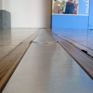
The rolling motion of high-point-load, small wheeled traffic can quickly cup under-designed coverplate systems as well as caused damage to adjacent flooring.
Higher Point Load Stress
In hospitals, floor expansion joints often deteriorate faster than expected. This phenomenon is caused not only by the failure to engineer for sufficient point load capacity, but also by the fact that hospital operations have been changing in ways that significantly increase point load stresses.
One such trend is “patient-centered design” that has taken root during the past decade. The goal of patient-centered hospital care is decentralization, which brings services to the patient, rather than transporting the patient to centralized locations for imaging, dialysis and other medical procedures.
Patient-centered design decreases the movement of patients, along with the unnecessary staffing, waiting, reporting and errors this movement entails. Patients remain in the relative comfort of their rooms, where they benefit from familiar surroundings. They are more comfortable, hospital operations are more efficient, and the spread of infectious disease is reduced.
However, this decentralization means more movement of equipment, as diagnostic and treatment apparatus is transported to patient rooms. This adds expensive and sensitive equipment to the already busy flow of cleaning, maintenance and food service equipment traffic at hospitals.
Much of this equipment is conveyed by small-diameter, hard wheels, which can and do cause damage to floor expansion joints and surrounding flooring materials that are not engineered to handle the high associated point loads. Equally as important to the damage of the expansion joints is the potential damage to the equipment itself.
Another trend increasing point loads at hospitals is the need to accommodate an increasing number of overweight patients as obesity among U.S. adults has increased more than 60% during the past 20 years.
In his article “Designing for the Obese,” Dave Barista, assistant managing editor of Building Design and Construction magazine, reports the findings of interviews with leading healthcare design experts. Numerous design considerations were advocated, including “everything from wider doorways and heavy-duty beds to patient lifts.” The article also mentions that “bariatric beds should be rated for at least 600 pounds.”
Not included in this article is the impact of these design considerations on floor expansion joint selection. Oversized wheelchairs, beds and gurneys are increasingly common in hospitals. Bariatric beds can weigh up to 800 lbs empty and, depending on the model, are rated to carry patients weighing up to 1000 lbs.
A combined load, for example, of bed and patient of 1,610 pounds, spread over four, 1-¼” (30mm) wide, hard rubber wheels, would result in a load per wheel of 402 lbs or 321 lbs per inch of wheel width.
1610 lbs = 402 lbs/wheel 402lbs/wheel = 321 lbs per inch of wheel width
4 wheels 1 ¼” wheel width
The expansion joint system intended to handle this load must be selected for its ability to handle this load without deflection. Compare, for example, the load capacity of 365 lbs per inch of wheel width of the FS 110 system.
Failure to select the expansion joint system based on this comparison could result in the specification of an inappropriate expansion joint product.
Types of Floor Expansion Joints
The design of floor expansion joints presents an engineering challenge. They must be able to handle transverse horizontal opening and closing movement, longitudinal differential or shear movement, as well as vertical differential shear movement. These requirements are similar to the movement demands of wall, ceiling and roof expansion joints. What makes the design of floor systems so challenging is that they must perform these movement functions while also providing a strong “bridge” that can bear point loads and provide a smooth, quiet transition for wheeled traffic, as well as a slip-free surface for pedestrians.
Manufacturers of floor expansion joints have used a variety of approaches, with varying degrees of success. The available products fall into three design categories:
Rubber and Rail Systems
The most common and least expensive system comprises two extruded-metal (usually aluminum) angles, between which an elastomeric filler is inserted or adhered. To enable expansive and compressive movement, the insert needs to be a soft, elastic material and/or shaped into a bellows form. However, soft materials and bellows shapes are incapable of resisting even relatively small point loads. Because the rubber material is soft, wheels sink in and bang against the metal angle on the far side of the joint. This results in a nasty jolt to patients and medical equipment, causes damage to the adjacent flooring, and results in early failure of the expansion joint itself.
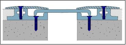
Cover Plate Systems
To provide better point load resistance, a second product category employs a metal plate. The plate can be anchored on one side [See Figure 2], can float between clamping plates [See Figure 3], or can be held in the middle with a centering bar. These systems provide a stronger bridge than rubber and rail systems, and they are capable of handling small to moderate point loads, although manufacturers regularly fail to provide point load ratings from which to match models to expected traffic loads. Most of these systems are especially poor at handling floor height differences or vertical differential movement which causes the cover plate to float unsupported at various locations. This phenomenon makes cover plates noisy, and when deformed by the torque of differential vertical movement, can result in a tripping hazard. Additionally, the gaps under the cover plates create cleaning problems, as moisture and dirt collects in the recesses–an unacceptable hygiene problem in a healthcare setting. Finally, because there is a transition on each side of the cover plate, wheels bump twice during transition over the joint.
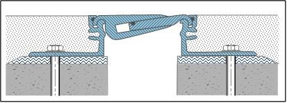
Solid-Interlocking Systems
A purpose-designed alternative interlocks two extruded metal components in a design that accommodates horizontal opening and closing,
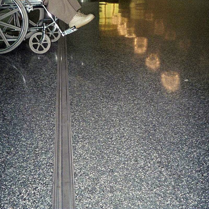
as well as differential lateral and vertical movements, while providing high point load resistance [See Figure 4]. This solid-interlocking system was specifically designed to withstand the pounding from small-diameter, hard wheel traffic, while respecting aesthetic integration with adjacent flooring materials [See Photograph 1]. The design provides a smooth, quiet rolling surface. Integrated gaskets that seal out dust and dirt are also thoughtfully engineered features for hospital environments.
Anchoring Systems and Epoxy Leveling Beds
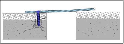
Another important consideration when evaluating floor expansion joint systems is the anchoring method. Mechanical masonry screws or “expansion anchors” supplied by most expansion joint manufacturers hold themselves into drilled holes by means of an outward pressure against the substrate. This creates a fault line close to the edge of the floor substrate, leading to fractures in the concrete edge. Spalling at the joint edge leaves the mounting flanges of the expansion joint system unsupported and liable to downward deflection under loads from above.
Better suited for expansion joint applications is the use of chemical anchors. Chemical anchors use a hard-setting epoxy adhesive to lock a threaded rod into a hole drilled in the concrete floor. This method ensures the necessary hold-down force without causing stress to the concrete.
Another simple installation practice that can substantially prolong the useful life of any expansion joint system, but particularly those in high point load environments, is the application beneath the mounting flanges of an epoxy setting bed. This ¼” (6mm) layer of epoxy mortar eliminates any unevenness in the substrate, which ensures that the mounting flanges are fully supported throughout their lengths. An epoxy bed also acts as a dielectric insulator between the concrete and the metal flange to prevent corrosion.
Costs of Failure
When point loads cause the failure of floor expansion joints, healthcare facilities incur significant costs. The uneven surfaces harm expensive mobile medical equipment and constitute a risk for personal discomfort and even injury. In addition to the labor and material costs involved in replacement of floor expansion joints, the real cost to hospitals lies in the disruption involved in closing off entire sections of the facility during the replacement process.
The initial purchase costs of high-quality floor expansion joints are more than for inexpensive rubber and rail or coverplate systems. However, this incremental cost is small compared to the long-term economic benefits of durable and trouble-free floor expansion joints that withstand the point load of expected healthcare traffic conditions.
“It is unwise to pay too much, but it’s worse to pay too little. When you pay too much you lose a little money—that is all. When you pay too little you sometimes lose everything, because the thing you bought was incapable of doing the things it was bought to do. The common law of business balance prohibits paying a little and getting a lot. It can’t be done. If you deal with the lowest bidder, it is well to add something for the risk you run, and if you do that you will have enough to pay for something better.”
— John Ruskin.